DrySummix® 4 Channel Summing Card
Installation Guide

The SB4TP signal trim junction box with transient protection is ideal for use in Floor Scales, Tanks and Hopper applications. This load cell summing circuit board is assembled in Orlando, Florida using high quality genuine electronic components.
Spring Terminal Block Connectors:
Color coded "Industry Standard" Terminals
Designed for 24-16 AWG wires
45 Deg Push-in WAGO CAGE CLAMP®
Signal Trimming:
Individual Cells
20 turn - Clutch Action Both Ends (Rated 200 cycles)
Factory Matched to be mid-range for quick calibrations
Temperature:
Operating = 0 °F to 122 °F (-18 °C to 50 °C)
Trimming Potentiometers:
TT Electronics Cermet 100K Ohm +/- 10%
Vibration rated - 20 G's at 10 through 2,000 Hertz
Gas Discharge Tubes (GDTs):
2KA 8/20μs maximum surge current capacity
Surface Mounted 75 Volt Micro Spark-Gap Design
Approvals:
ROHS
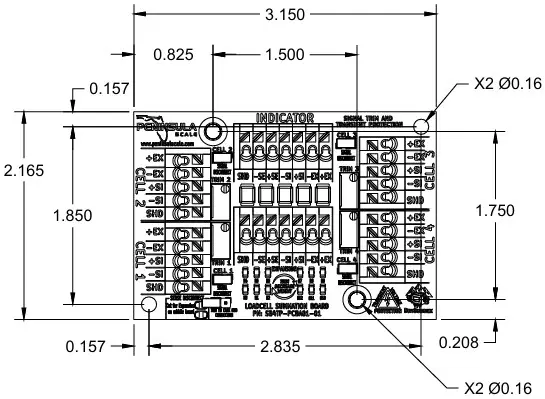
Circuit Board Dimensions:
.65 inches tall
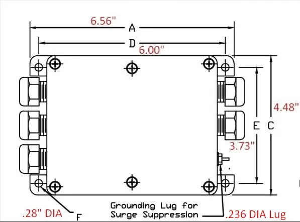
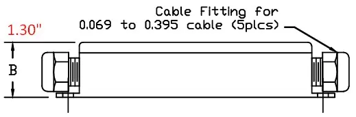
ABS Low Profile Enclosure
Intrinsically molded ABS with liquid tight gaskets
Cable Sizes from .069 through .395
Stainless Grounding Lug is xxx dimeter
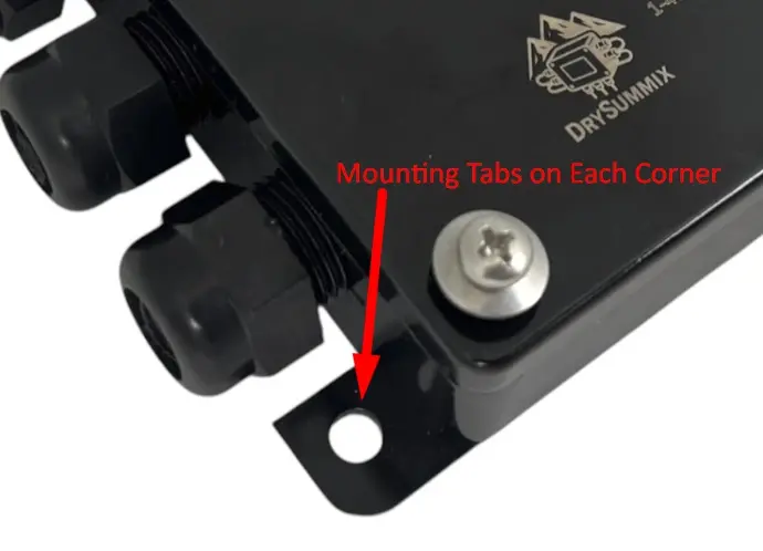
Mounting tabs on each corner are xxx diameter
Standard ABS Enclosure
Coming Soon!
Stainless Steel Enclosure
Coming Soon!
Features to Consider:
- German Made WAGO color coded terminal blocks for easy identification of excitation, signal and sense for quick (reading glasses free) installation
- The expansion terminal allows connection of multiple junction boxes to connect up to 24 loadcells
- The signal disconnect jumpers allow isolation of individual loadcells which allows 1, 2 or 3 loadcells to be used per summing board
- The gas discharge tubes and grounding lug provide transient surge protection for your loadcell system blocking harmful voltage spikes that can be transmitted through the homerun cable
- Easy to read durable laser markings on the enclosure provide recommended wire stripping lengths & quick QR Barcodes to installation documents
- Loadcell Numbering, Excitation, Signal and Sense markings are large and easy to read on the printed circuit board
- large and high quality rechargeable desiccant packs included standard to guard against moisture buildup in humid climates
- Circuit boards are solidly mounted to the enclosure with brass inserts & stainless hardware so you don't have to worry about shoddy adhesives coming loose from heat and vibration
Consider the following factors when installation of a DrySummix junction box on your next scale application
- Ease of serviceability
- In floor scale applications, ensure the enclosure fits into the scale deck before proceeding
- Can you easily reach the front cover and have enough room to open the lid with the proper tool?
- Is the box oriented to easily read markings and insert wires into the terminal blocks?
- Can you tighten the cord grips onto the loadcell wires easily and reliably?
- Environmental
- Will the enclosure be in the way of other production, cleaning, or maintenance processes for the customer
- Ensure the mounting structure is solid and won't be relocated by customer staff or likely to be damaged
- Protected from splashing of customers product, cleaning chemicals or moisture
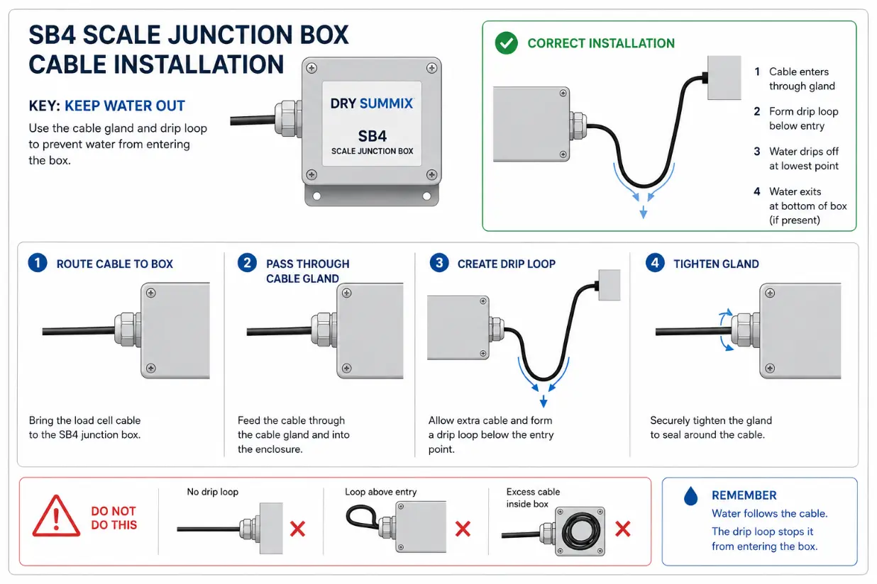
- Include "drip loops" so that any moisture accumulating along cables drip off before going into the cord grips
- Are there any heat or vibration factors that should be mitigated
- Electrical
- Proximity to grounding rod or single point ground for transient protection
- Allow easily running of load sensor and instrument homerun cables along existing conduit or scale/tank/hopper structures
- Avoid running any of the low voltage scale signal lines near any high voltage pump, motor or power lines to reduce the potential for electrical noise to be present in the weight signal
The junction boxes can be mounted specific to their enclosure types listed below
Low Profile ABS:
Mounted using standard pan head screws through the mounting tabs on each corner. Designed for 1/4-20 standard hardware as the hole is .280 inches. Number 12 or Metric M6 hardware is a good choice.
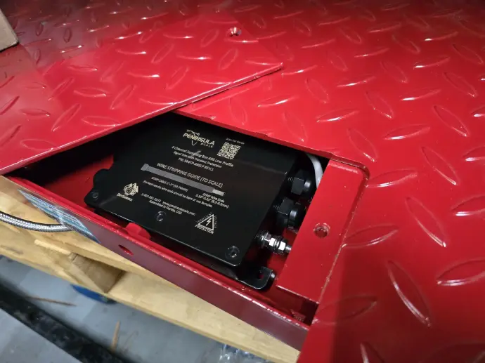
Most low profile summing boxes are simply placed into a cavity inside of a floor scale or other enclosure already mounted for the device. Below you can see the summing box nested into the cavity of the floor scale deck and then the cover plate is put back onto the scale deck.
Ensure the enclosure fits into your floor scale before wiring it up, there is a lot of variance in sizes between different scales and you should always check it fits before proceeding with wiring.
Standard ABS:
Coming Soon!
Stainless Steel:
Coming Soon!
(Need a picture of the scale deck and the loadcell numbers outlined with the board corresponding to cell numbers)
Determine the layout of the loadcells that you would like to connect, typically you would lay the board out flat in front of you and each loadcell is wired to the corner of the board that it is closest to. This way when trimming later it is intuitive which cell number you need to adjust based on where the weight is placed on the scale deck.
Determine the wiring pattern to be used (diagram needed here)
2. Route the load cell cables through the cord grips, do not tighten the grips.
3. Strip the wire insulation back 1/4 inch to expose the wire.
4. Push in and hold the quick-connect lever with a small screwdriver.
5. Insert the appropriate wire into the exposed wire opening.
6. Release the screwdriver to allow the spring-loaded gate to close and lock the wire in place.
Need to have a guide on how to wire the single point ground to building or ground rod
We will need to show how to setup multiple boards daisy chained and what to watch out for
This will also need to be mostly Jeremy to help with this as I am not sure what to include???
Follow the steps below to properly trim the DrySummix SB4TP loadcell summing cards for accurate load cell balancing and scale performance.
1. Determine the Number of Load Cells
Identify the total number of active load cells being used in the scale system and which orientation the box is mounted so that the position the cells are connected makes sense if you were to lay the board flat in front of you
(Picture of floor scale here) with picture of the summing board pointing from loadcell to board laying flat
2. Verify Wiring and Set the Jumpers
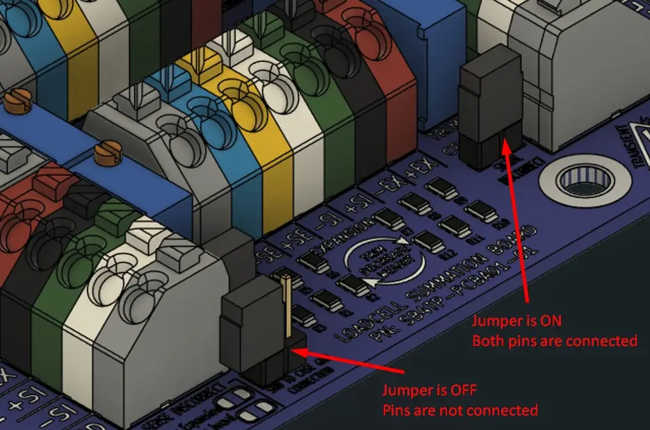
Verify that the jumpers are ON (connected) for all active load cells to enable the trimming functionality for that loadcell. You MUST Remove jumpers (OFF or not connected) for any unused load cell positions. You can easily set the jumper onto a single pin so that it is stored with the board should you need it later or you can remove it completely and keep as a spare in your parts kit.
3. ALREADY SET Initial Potentiometer Positions
It is NOT recommended to adjust your potentiometers from their current positions.
Each potentiometer is set from our factory at the exact "Mid-Range" (52K Ohms) for each loadcell channel. This methodology is a tradeoff for overall trimming range (difference you are able to adjust between the two furthest cells) and the speed/ease of minor adjustments to the device in the future.
Since the potentiometers are set to midrange, any loadcell can be easily adjusted up OR down to trim minor differences. This prevents having to completely reset all loadcells and trim multiple cells for a small error on a cell that has run out of adjustment range because the potentiometers have already been maxed out.
4. Prepare the Indicator
With the scale unloaded, zero the indicator according to the indicator manufacturer’s instructions. It may be best to put a preliminary calibration on the scale so that the weight values displayed are close to what you are expecting once finished. This ensures that you are not chasing a corner error that won't be visible when the final calibration is applied.
5. Apply Test Weights
Place calibrated test weights directly over each load cell, one corner at a time. Being precise in the where the weight is applied to each corner will help with trimming corners quickly.
The amount of weight used will depend on the scale capacity and configuration. Recommended Practice: For a four-load-cell platform, NIST Handbook 44 recommends using approximately 25% of the scale’s total capacity as test weight. Typical floor scale trimming is done with 500lb or 1000lb block weights on each corner at minimum.
6. Record Displayed Values
Record the indicator reading for each corner after the test weight has stabilized. Ensure the weight is centered directly above the load cell and does not overhang the platform.
(picture of 500lb weight on floor scale corner)
7. Verify Return to Zero
After removing the test weight from each corner, allow the scale to return to zero. This helps identify friction, binding, or other mechanical issues. These must all be resolved prior to attempting any electrical adjustments like we are doing in this procedure.
8. Establish the Reference Load Cell/s
Identify the load cells that match each other. Typically two or three cells will be the same and the other cells will be slightly different from your nominal value.
If you had already put a calibration into the instrument with certified test weight we will plan to adjust the cells that don't match nominal test weight value
9. Trim Remaining Load Cell/s
Place the same calibrated test weight over the loadcells that did not match in the corner in the same exact place your originally set them
10. Adjust the Corresponding Potentiometer
Using the matching potentiometer, adjust the output of that load cell until the indicator reading matches the reference load cell value/s or matches the nominal test weight value.
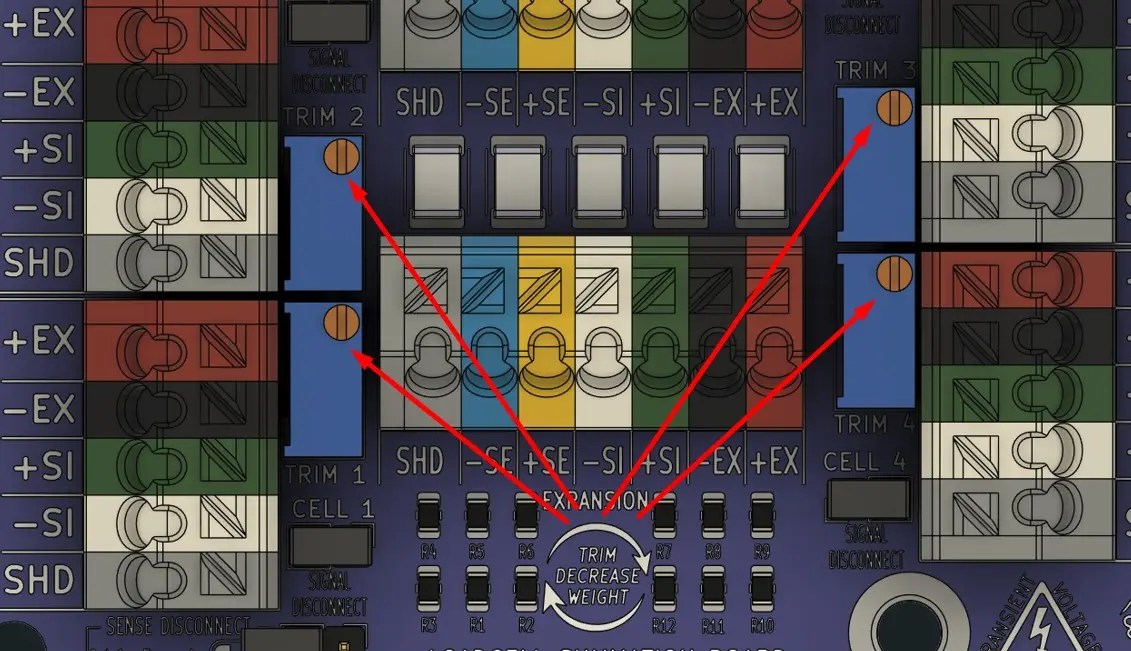
The trim direction is shown in the center of the circuit board with the rotating arrows:
To the right (clockwise) decreases the weight shown on the scale instrument
To the left (counter clockwise) increases the weight shown on the scale instrument
If your weights are behaving opposite then you have the signal wires from the loadcell connected backwards OR you have the loadcells mounted into the scale upside down
11. Repeat for All Remaining Load Cells
Continue the trimming process for each remaining load cell until all corners display equal readings.
12. Verify Repeatability
Recheck all load cells for consistency and repeatability. If necessary, repeat the trimming procedure until all corners are balanced accurately. It is very important that once you feel you are completely done with adjusting the potentiometers that you go back and set the test weight on all of the other cells to ensure none were affecting by your most recent adjustment.
If all of the cells are displaying the nominal value of the test weight then you can proceed. If they are all the same but a few divisions from nominal then you must refer to the calibration documentation for the instrument it is connected to and perform a zero and span calibration to make the scale display the accurate nominal test weight value.
13. Install Desiccant Drying Pack
Place the supplied desiccant drying pack inside the junction box to help protect against moisture and condensation. It is recommended to tuck it down into the box away from the circuit board or wires. Should the pack become saturated with water we want it as far away from the board as possible for the most reliable experience for the end user.
14. Secure the Junction Box Cover
Replace the cover and tighten the screws evenly in an alternating cross pattern to ensure proper gasket compression and environmental sealing.
(Image of the top box with screws going in numbered in a cross pattern)
Important Maintenance Note
Inspect the desiccant during routine service intervals and replace it as needed to maintain moisture protection and long-term reliability especially in humid climates
Next time we do some board assembly we need some images of removing the board and installing a new one in the ABS enclosure
Low Profile ABS:
Standard ABS:
Stainless Steel:
Best easiest way to check any of the terminal blocks with standard multimeter prongs
fastest way to check the signal wires for the millivolt signal from the loadcells
Notes on the standard values you should find at each location
we will need how to check if the GDTs have been blown
how to check if the pots are balanced
how to check for good grounding to single point location
DrySummix 4 Channel Replacement Part Numbers
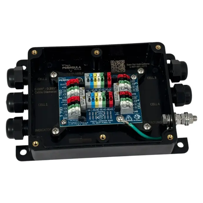
Low Profile ABS 4 Channel
With Transient Protection, built for tight spaces like floor scales & OEM equipment like pallet wrappers & mixers
Part Number: SB4TP-ABSLP
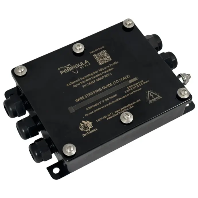
Standard ABS 4 Channel
With Transient Protection and enhanced mounting options for Tanks & Hoppers for quick professional installations
Part Number: SB4TP-ABS